Wednesday, 02 September 2020
How to use a 4-20mA Current Loop

In this post, Intempco will teach you how to use and troubleshoot a 4-20mA Current Loop. For a visual guide, watch Intempco’s video tutorial.
What is a 4-20mA Current Loop?
A 4-20mA current loop is the most common output in industrial control systems because it is very resistant to electrostatic discharge, is not affected by change in voltages in the system, and has a non-zero number as the low point. This quick demonstration will show you how a sensor uses a 4-20mA current loop to indicate a measurement and how to troubleshoot these systems.
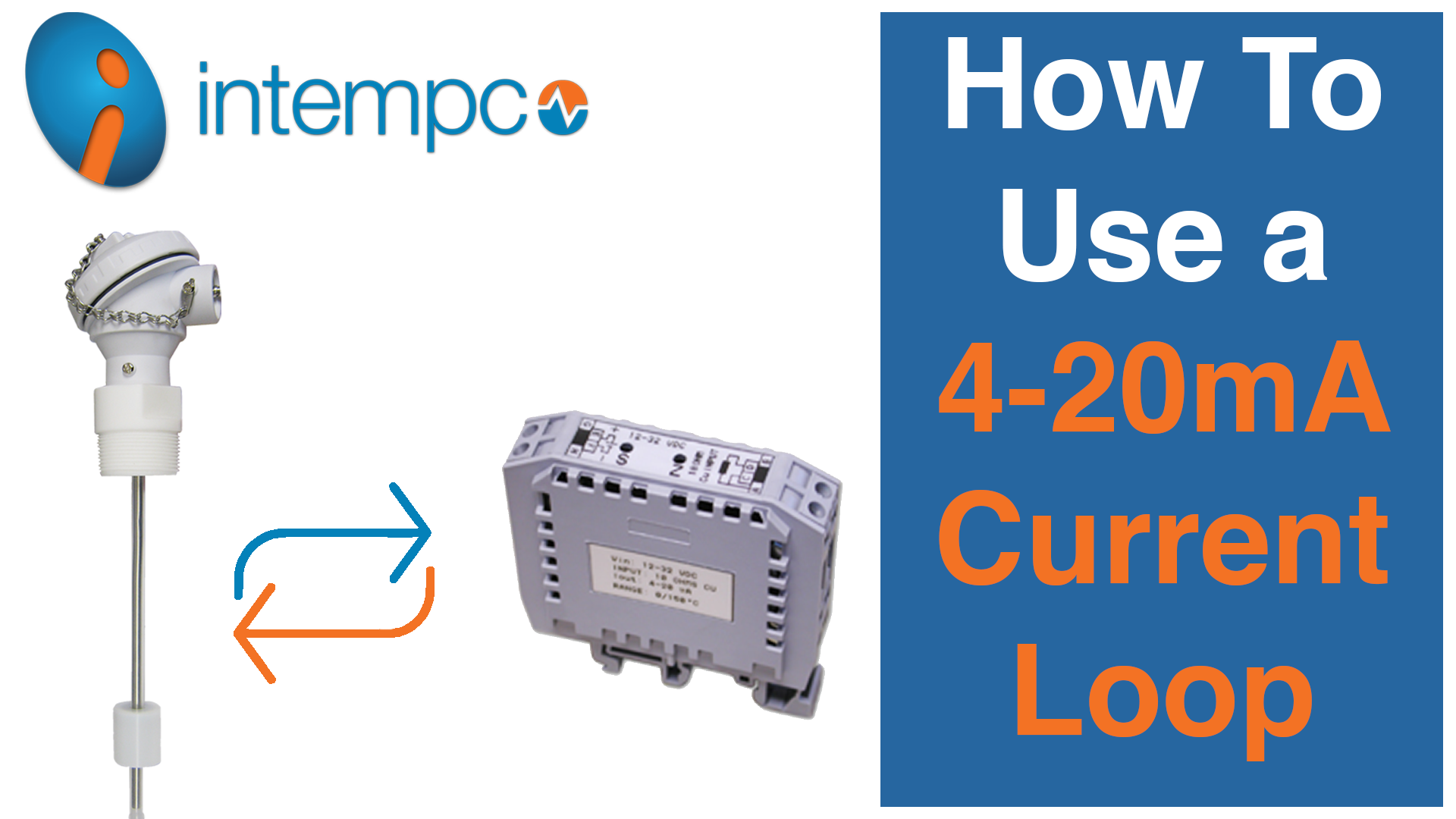
We will be using an Intempco float level sensor for this demonstration. This sensor changes resistance with a change in float position. Attached to the sensor head is a transmitter that converts the resistance into a 4-20mA current signal. The transmitter is powered with a negligible amount of power from the loop, so it does not affect the measurement.
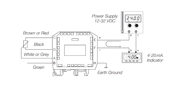
There are four connections from the sensor to the transmitter. They are Top, Bottom, Signal, and Shield. The connection locations and wire color are printed on the side of the transmitter.

Steps to Create a 4-20mA Current Loop
Step 1
Hook the transmitter up to a variable power supply with an ammeter in series with the circuit.
Step 2
Connect the positive of the supply to the positive input of the transmitter that is into the loop positive input of the transmitter.
Step 3
Connect the output of the transmitter (the loop negative) to the input of the ammeter.
Step 4
Connect the negative of the ammeter to the negative of the supply to complete the circuit.
Step 5
Set the power supply to 24 volts and the sensor at the bottom position. The current reading will be 4.00mA and shows that the float is at the bottom of the sensor span.

Converting 4-20mA to 1-5V
-
Break the loop and insert a 250-ohm resistor in series. A series resistor is used to convert the current signal into a voltage signal.
- With the circuit restored, you can see the ammeter is still indicating the same current as it did before we inserted a resistor.
- The embedded processor inside the transmitter will maintain the proper current despite changes in voltage or resistance in the circuit.
- If we put a voltmeter across the resistor, we can see at the mid position it will show a voltage drop of 3 volts. We can calculate this using the equation.
Current X Resistance= Voltage
For 4mA: 0.004A X 250 Ohms= 1 volt
For 12mA: 0.012A x 250 Ohms = 3 volt
For 20mA: 0.020A X 250 Ohms = 5 volt
- Here, we can see that a 4-20mA current signal can be converted to a 1-5V signal.
Minimum Voltage Requirement
There are limits for how big of a resistor you can use in a circuit like this. The embedded processor in the transmitter needs a certain amount of voltage overhead and current to function. This can result in the processor losing its ability to function and showing improper readings. To determine the maximum loop resistance for out transmitters, use the following equation.
Maximum Loop Resistance
(Vsupply- 9V) / 20mA = Max resistance in Ohm
For 12 volts (12-9) / 0.02 = 150 Ohms
For 24 volts (24-9) ‘ 0.02 = 750 Ohms
For a given resistance of 250 Ohms, the minimum required voltage would be 14 volts.
To show the effect of having two large resistance, change the resistance to 500ohms.
The transmitter isn't able to function properly. To be able to function with this resistance, you would have to raise the voltage level.
Poor Sensor Connection Leads to Open Circuit
Another possible failure scenario would be a bad sensor or sensor connection. If you remove one sensor head between the transmitter and the sensor to simulate this you will see an open circuit on the sensor.
These are the basics for a 4-20 mA current loop or any other pressure, temperature or humidity sensor.


