Thursday, 25 June 2020
What is a Temperature Transmitter?

Many aspects need to taken into consideration when choosing a temperature transmitter. Here's a five-step guide to choosing the right one for your application.
How to Choose the Right One for your Application
What is a temperature transmitter?
A temperature transmitter is an electronic device used to send a temperature measurement over two wires to the processing unit. The transmitter is responsible for converting the small electrical signal from the temperature sensor into a more readable signal for the processing unit. In most cases, the signal is sent to some sort of programmatic logic controller (PLC) or receiver.
If you are thinking about using thermocouples, resistance temperature detectors (RTDs), or thermal resistors and are wondering how to communicate their micro-signals to the industry standard 4-20mA, then you must use a transmitter.
Transmitters are commonly referred to as transducers because of their close proximity in definition and can be used interchangeably.
Transmitters are physically designed to accept and deliver many different types of inputs and outputs. They require a power supply voltage and have different physical shapes depending on your application.
How do temperature transmitters work?
Transmitters aim at amplifying and filtering the signal from the temperature sensor. How this is done varies slightly based on the sensor in use.
For example, when using a RTD, a Wheatstone bridge is used to create a small voltage across its extremities. This signal is then amplified to produce a 4-20mA signal. Sometimes, this analog signal is converted to a digital signal (ADC) to allow for additional functions (such as calibration and scaling), then returned to an analog signal. The conditioning circuitry can be designed for resistance values from 15 to 380ohms or something similar to accommodate the full range of RTD values.
The electronics inside the transmitter will draw 4mA from the power supply when the temperature is at the low-end setpoint and will draw 20mA when the sensor is at the high-end temperature setpoint. For example, if your temperature range of your sensor is 0-100 ℃, then a 4mA signal would correspond to 0℃ . In the same way, 20mA would represent 100℃. Using 4mA as the low reference makes it much easier to notice when your system is malfunctioning. That being said, transmitters are designed for numerous inputs and outputs.
What are the inputs of a temperature transmitter?
The most common types of inputs for temperature transmitters are thermocouples and RTDs.Thermocouple Input
In the industry today, transmitters for thermocouples are normally designed for the base metal thermocouples. Those are type: K,T, J, and E. That doesn’t mean that you won’t be able to find transmitters for other types of thermocouples but they may be more expensive.
Thermocouples have two wires, so the transmitters will have two input terminals where the wires can be connected. It is important to wire the thermocouple correctly. The transmitter should be purchased with cold junction compensation. Cold junction compensation is used as a reference for the junction that is immersed in the environment.
Thermocouple transmitters will have a Zero and Span dialog that will be used for calibration purposes. You must fine turn the device using these potentiometers, if you notice your device is reading incorrect values.
Resistance Temperature Detector (RTD) Input
RTD inputs are designed based off of their resistance value. The resistance is known by the material used when creating the wire-wound. Platinum is a commonly used material and has a temperature coefficient of 0.00392 //℃. From this, it is possible to make a wide variety of resistance values. They can range from 10 to 10,000, but the most common is 100 known as a PT100.
Once you know the resistance value of your RTD you're halfway done specifying the input for the transmitter. The next step is to decide on the number of wires for the RTD. RTD are made in 3 different wiring configurations: 2-wire, 3-wire and 4-wire. Each topology requires slightly different circuits. The 3-wire configuration tends to be the most economical and provides sufficient accuracy and precision. Although, you will be able to find transmitters for all types of wiring.
Thermistors are used when the temperature range is small, but the response needs to be high. If you need a transmitter for a thermistor they can be sourced similarly to a thermocouple.
What are the outputs of a temperature transmitter?
Temperature transmitters act as the medium of the sensor and the receiver, thus they should output a value that is measurable by the receiver instrumentation. Across the industry, the standard output of a temperature transmitter is 4-20mA, 0-5VDC or 0-10VDC.
What are the physical forms of a transmitter?
The three main forms of transmitters are DIN rail mounted, hockey puck, and microprocessor based. By reviewing each form of a transmitter, you will get a clear image of the benefits of each type and this will help you choose the right form for your application.
 DIN Rail Transmitters
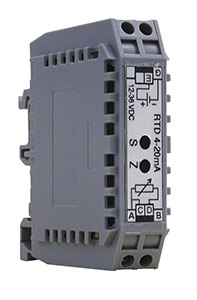
The DIN rail transmitters (named for their original German specifications) tend to be used when the application requires an electrical box or a surface that requires DIN rail.
DIN rail is an industry standard mounting hardware. You can see on the bottom of the transmitter there are mounting brackets. They are very easily snapped onto the DIN rail. This form of transmitter should be used when space concerns and protection is a large part of your design. You can guess from the durable plastic enclosure that it is well suited for industrial environments. Their size is modular, which makes them a great choice for saving space. The performance of DIN rail transmitters are very accurate and precise. The screw terminals make for quick wiring and they accept a wide range of wire gauges.
 Hockey Puck Transmitters
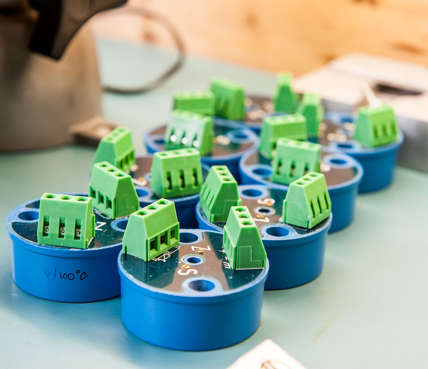
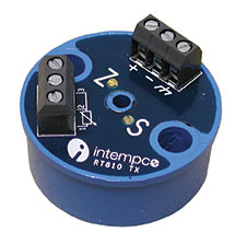
The famously known “hockey puck transmitter” got its name from its form factor. These are used for basic applications and are the most common transmitter. They are also well suited for OEM applications and are low cost. These transmitters are suitable to be put inside the heads of temperature probes. They have two mounting holes on each side of the device. They are designed to be small and to limit the amount of installation hardware.
Microprocessor Based Transmitters
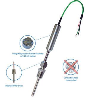
Microprocessor based transmitters are unique as they can be integrated directly onto the temperature sensor. This advanced model made its debut in the industry approximately 25 years ago. They have excellent durability as they are enclosed in a steel structure and are completely sealed. They are programmable which means that their temperature range can be scaled after fabrication. This is useful when there are changes to the temperature range and the accuracy needs to remain high. This is more commonly available with RTD sensors. It provides a compact appearance and lowers the amount of wiring needed during installation. The additional cost savings on labor during wiring makes this form affordable. Their standard outputs are 2-wire loop powered 4-20mA or 3-wire voltage outputs.
What industries use temperature transmitters?
Since the 1950s, when electronics really began to reach mass market, transmitters have been used in every major industry where temperature sensors are present:
-
Aerospace
-
Chemical
-
Food & Beverage
-
Energy
-
HVAC
-
Pharmaceuticals
-
Metal Plating
-
Mining
-
Oil & Gas
-
Petrochemicals
-
Waste & Water Management
-
Electronic OEMs
How to Choose the Right Temperature Transmitter:
-
Understand the functionality of a temperature transmitter
-
Identify the inputs
-
Identify the outputs
-
Identify the power supply
-
Find the supplier
-
Understand the functionality of a temperature transmitter
If you haven’t already, you should take the time to read the sections above to get a solid overview of the functionalities of a temperature transmitter.
A few considerations to take into account before moving on to the next step:
-
Where will the transmitter be mounted? In what type of environment will it have to function?
-
How costly would a measurement error be? This will determine the degree of sophistication your transmitter will require.
-
Does the transmitter need to be programmable?
-
Identify the inputs
Depending on whether you are using a thermocouple or RTD, you must select the appropriate inputs. This is dependent on your sensor. The temperature range and precision should be used to determine the type of thermocouple and RTD you wish to choose. For example, a type-K thermocouple would be used for a temperature range of -200 to 1,260 ℃.
-
Identify the outputs
You should be able to examine your programmable logic controller (PLC) or your data acquisition unit and determine which type of outputs should be sent from the transmitters. This will most commonly be a 4-20mA signal, but 0-5VDC and 0-10VDC are also standard outputs.
-
Identify the power supply
The power supply will be something you must decide upon yourself based on the other components in your system. If you have electronics operating at 12VDC, then it makes sense to use 12VDC as your power supply. If you don’t have any requirements, then use 24VDC as the power supply. This is the industry standard.
-
Find a supplier
Once you are ready to purchase your transmitter, it is important that you find a supplier that is capable of meeting your demand. Find the datasheet for the product that you think best fits your inputs, outputs, and power supply, then verify all requirements on the datasheet.
Make sure to take your time. Choosing the right transmitter for your application requires a clear understanding of how it will be integrated in your processes, what exactly your needs are, and how its environment might affect its performance.
Finding a supplier that can assist you and answer your questions is essential when selecting a transmitter for a new application.
 Combined Temperature Sensor and Transmitter
Here at Intempco, we have combined a traditional RTD sensor with a transmitter to create the MIST™ Microprocessor Integrated Sensor Transmitter. The MIST simplifies designs by eliminating the need to have both a temperature sensor and a transmitter. The output of the MIST is either 4-20mA, 0-5VDC, or 0-10VDC. This is a compact design that has been used across all industries and proves to be a reliable solution.


